The Maquette of the Zeppelin-Staaken R.VI:
Roden 1/72 Zeppelin Staaken
When Piet Steen came down with his question, I first started to search on the Internet whether such a kit existed and whether it was feasible to accept the assignment knowing that a "deadline" was attached to it.
According to a fellow model builder in New Zealand, who had just completed a Stakes at that time, it was feasible to finish the kit within six months; a problem: I had only three months at my disposal !! But ... a little healthy stress must be possible and the how and what was agreed with Piet.
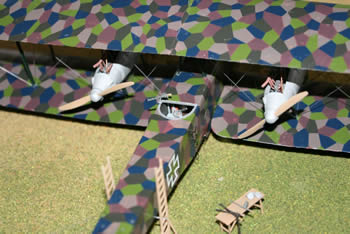
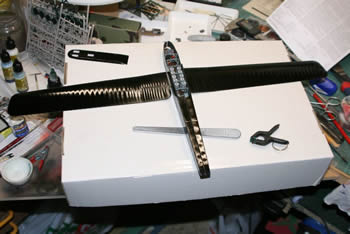
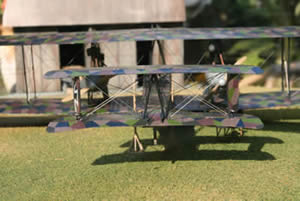
When the kit arrived, it turned out that the contents of the box could be called impressive: 11 windows with pieces and pieces and some full A4-sheets on which the decals of the Lozenge camouflage. The Lozenge motif was a German way of camouflaging during the First World War with irregular colored polygons: consisting of either 4 or 5 colors; well that the camouflage was supplied as a decal because it was to spray or paint it out of hand .... It also became immediately clear that the model would get impressive dimensions in its finished form. Before his time it was the largest aircraft and it was only in the Second World War that the Boeing B-29 with a 1.5 m larger wingspan crossed the Staaken.
Those were problems for later! After a thorough introduction to all parts, I started painting all small parts such as the ladders, machine guns, parts of the engines, petrol tanks, the actual preparatory work.
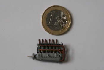
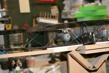
Then I started with the merging of the 4 engines; each engine, when it was finished, consisted of 23 parts that all had to be painted in the right color: copper cooling water pipes, rust-colored exhaust pipes (all of which I had drilled with a 0.2 mm drill bit to get a more realistic look!) 6-cylinder-in-line engines so 24 pipes ... ..)
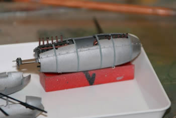
Then 2 engines had to be placed back-to-back in their gondolas (engine gondola1); the 2 front engines had tensile screws, the 2 rear thrusters. There were 2 gondolas with between the engines a place for the technician who during the flight (up to 8 hours !!) the engines maintained and / or repaired. The cooling water pipes that ran to the radiators above the engines, I made from fine copper wire. The sad fact was that when the gondolas were finished, there was actually little to see of the many work I had spent on the engines!
Then the regular e-mail traffic between Piet and me started regarding the colors to be used.
Piet actually wanted me to paint the model of the Zeppelin Stakes as faithfully as possible in the colors of "his" R.34 / 16, so I had to deviate from the accompanying color scheme and Piet had to continue his instructions.
During the construction of both gondolas both inverted "V" struts, which held the gondolas in place between both wings, had to remain loose so that the gondolas could be placed in the right place between the wings.
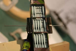
Then it was time to complete the interior of the bomber first; the 10 petrol tanks got their place and the rest like the chairs and the ribs and rafters had to be put in place. However, it appeared that of all the effort I spent on the interior, there was nothing to see after the closure of the hull!
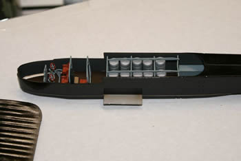
That is why the opened bomb doors were replaced with new plastic plates, temporarily secured and there over the camouflage; after complete drying, the plates could be detached, cut to size and I had camouflaged bomb doors. (the latter are glued in open position, the bomb load is visible) Also I had to try to ensure that the camouflage on the edges of the hull continued, provided a little fit and measure (and a bit cheating) I succeeded!
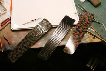
At the time of its crash, the R.34 / 16 was used for night bombardments; to get the right shade in the camouflage, I first sprayed the entire unit in shiny black (in the plans one speaks of a red-brown primer, but I think my black has given good results). When the decals were applied to it, I got a darker look which better suited the concept of a night operation.
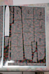
Before applying the decals to the large wings, the plan states that the decals must be cut in 3 parts in order to facilitate the application.
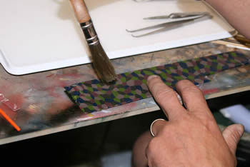
The New Zealand colleague, however, had mentioned that it was better not to follow this guideline because if the decals are wet, they become a little stretchable and then there would be a chance that you would not be right next to each other the different squares of the camouflage. get with all the problems of that. If you know that a wing half is a thick 30cm long, you know at once that it would be a "nice" job if you tried to apply the decal in its entirety. The "biggest" problem, however, was to find a scale where you could completely submerge the 30 cm decal. But the fuller wins and with sufficient use of Sol and Set the decals were nicely on the wings.
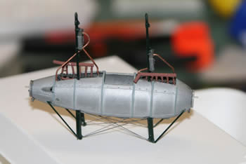
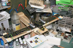
After that problem was solved, I could start with the following: placing the two main wings correctly. Strangely enough, the upper wings had to be placed somewhat more to the rear opposite the lower one. After the lower one had just been attached to the hull, I had made a kind of mold in which the entire model could be fixed; This way I could provide supports to place the top wing well. the bottom one. First both engine nipples were placed left and right, then I put the upper wing, which had already been put together, in position. Sometimes there was some consultation with God the Father, but in the end the top wing was glued to the struts and in the right corner! Only then could I place the central support under the central fuel tank; those legs had to be adjusted a bit!
What is characteristic of a biplane is the tension between both wings and all stuts; i.e. All the wires you see run between both wings and the vertical styles. That actually creates the strength of the wing as a whole. At the Zeppelin Staaken this was also very visible and there were striking differences between the devices depending on the factory where they were built.
Again Piet was an incredible source of information to know which wire should be placed in which place. For that I used piano wire of 0.5 and 0.3 mm; annoying to cut to size, but handy because there is already a certain stiffness and that helps to get a tight whole! It is best to start in the middle and so on the tips of the
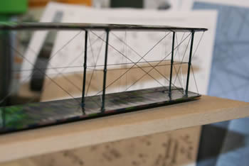
to work. Here it is also necessary to work quietly and deliberately because if you forget a piece somewhere ... .. then put a cross over because you can not even use 2 tweezers to get everything in place !! It is also best (I think!) That you first apply the tensioning cables between the two main wings before you start placing the tail section, you have to hold the model in the craziest positions from time to time, but only that one cable on its right a place that does not get in the way of the wide, fragile best! If the wiring of the main wings is successful, the next challenge can be started. The whole tail structure I started to place.
The biggest problem there is to ensure that everything is nicely perpendicular to each other and opposite the main wings; when fitting the main wings, it is also important to pay close attention to the dihedral of the lower wing: ie. the tips of the lower wing are higher than the attachment to the trunk. I also reinforced that attachment a bit by letting a thicker model of steel wire through the bomb compartment run from wing to wing. It is very important that during construction the mold is always supporting the lower wing during the construction phase until the cabling is finished! Only then can the model be removed from the mold; it is even true that the device in real life, when it was on the ground, had supports on the wing tips, to give extra support to the wings on the ground.
These are included with the model and are therefore just as necessary to support the model wings because otherwise they will sag through their weight and even damage the cables that are difficult to install !!
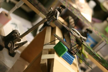
If the tail structure is complete, there is also the cabling there. The best thing is that you take a lot of time to study the available photos, because it is a tangle. Each wire actually has its function: there are rudder cables and they run best with the corresponding rudders (The "real" control cables I have made with brown, nylon fishing wire 0.08 mm thick), there are miniature cat rolls on which these cables run and it really pays trouble if you take some time! And in addition, you can do model building as relaxation!
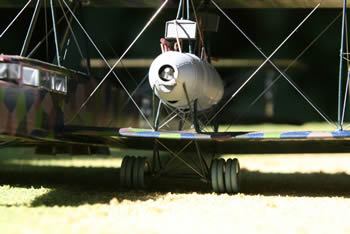
If you have survived that phase, the model may be out of its template and then you can start on the undercarriage. To allow the then incredible weight of almost 12 tons to leave on the grassfields, the aircraft was equipped with no less than 18 wheels. As usual at that time, I equipped the landing gear with "sandows". These were actually long elastic cables (or stretchers!) That were wrapped around the frame of the chassis and acted as shock absorbers 'avant la lettre'. In model you can achieve that by wrapping a few centimeters of yarn around and securing with some second glue.
Finally, I have replaced the small steps that are attached to the side of the hull to allow the crew to climb aboard, made with own made from leftover piano wire that gave a much finer result than the supplied plastic copies. Gluing the machine guns in their proper places was one of the last things I did on the model.
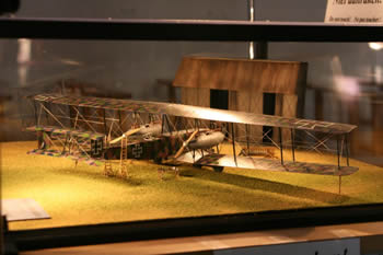
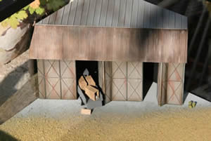
During the assembly of the model, there were often times when it became too much and that I had to do something else: Piet needed the Zeppelin Staaken model for an exhibition. That means: many visitors (hopefully!) And usually they have the annoying tendency to just 'watch' with their fingers. And I could not afford that pleasure to everyone! That's why a display was made, but an ordinary "tray" would also not meet. That is why I made a piece of the front of a hangar in the corner, with examples of the hangars used by the Germans during WWI. A patch of grass matically mimicked the Flemish grass fields.
The Zeppelin-Staakens R. VI were either equipped with either Mercedes D.IVa of 260 hp or with the better Maybach Mb.IVa of 245 hp. Both engines are therefore provided in the construction box. Since the R34 / 16 Mercedes engines had, of course, those engines were used for the model. The other 4 Maybachs engines I could use for the diorama. A model of an old truck from that period, from what garbage made a few crates and there was just a load of engines arrived, one crate was already broken so that one could see the engine in the crate! A trestle table for the surplus machine guns that were in the kit and the gunmaker could start his maintenance!
The only thing that is still missing (I have found some candidates in the meantime, but at the moment a bit of time is missing ....) There are some figures. They could bring some life into the whole. If I want to do what I have in my head, I have to do some research on it. the right colors of the uniforms of then and then a moment of rest and one of hatred between some orders and life comes into the shop!
During the first searches and the first weeks of building, I often went to look at different sites; New Zealander's building description often helped me because that man announced the problems that I could expect and then I could anticipate that. For those who want to start: it is a beautiful model but some (?) Experience is much needed! It is not a kit that simply falls into each other's hands, Piet and I have found several sites where people started their construction report and at a certain moment died a silent death or where I clearly saw that they did not follow the plan or even made "improvements" or that there were clearly errors (things I had had problems with, for example). Another important aspect: it is a BIG model and you need a lot of space.
Now I am a volunteer at the Stampe-Vertongen Museum at the Deurne airport near Antwerp and because the collection of the museum is situated from the start of aviation in Belgium to the Second World War, I have been given the opportunity to exhibit the model there.
I also have to thank Piet because, as a result of his call, I have been given the opportunity to create this beautiful model and to delve into a part of the aviation history that is not so well known in part. A history that was written and rewritten daily by the pioneers of that time.
If there are candidates who feel called to build the Stakes, this intrepid may always e-mail me, I will try to assist the candidate with consoling words and hopefully some advice.
Email: carl.gootzen@scarlet.be
It is doable but do not underestimate it !!
If there are people who want to come to visit the Stampe Museum (www.stampe.be), we also arrange guided tours in the museum; for larger groups we split the group into smaller groups and we work with several guides.